
DS3 Failover (DS3 Automatic Protection) APS Switch
Orion Telecom Offers Power Utility Solutions Oil & Gas Networks Solutions Railway & Metro Rail Solutions PTP IEEE-1588v2 GPS Primary Reference Clock Packet Optical Transport Multiplexers Teleprotection SCADA, FOTE, OLTE Digital Cross Connects Echo Cancellers IP/Ethernet over TDM 1+1 APS (Fail-Over) Solutions Monitoring Groomer Solutions
Product Overview
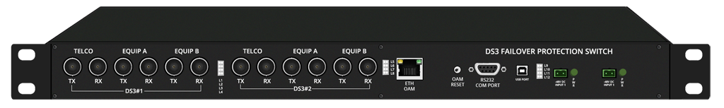
DS3 Protection (Fail Over) Switch allows the user to connect a single DS3 line from the telephone company to an "active", as well as to a "standby" DS3 terminal, such as data server, router etc. at the customer premises. In the event of a terminal equipment failure at the customer premises, the DS3 Protection (Fail-Over) Switch automatically "switches" the DS3 line from the service provider to the standby (working) DS3 terminal.
DS3 Failover (DS3 Automatic Protection) APS Switch - Presentation
DS3 Failover (DS3 Automatic Protection) APS Switch - Data Sheet
How it works?
In the event of the failure of the data server / router connected to the "A / active" port of the DS3 Protection (Fail-Over) Switch, the DS3 line from the telephone company shall automatically be "switched" to the data server / router on the "B / standby" port of the DS3 Protection (Fail-Over) Switch. This ensures minimum downtime - which would have otherwise occurred due to equipment failure connected to the "A / active" port. This equipment may be used to enhance the reliability and the efficiency of the customer's data network.
Application Note
The DS3 Fail-Over Switch should be used when the customer wishes to connect redundant (active and standby) DS3 equipment (such as Routers) at the customers premises to a single DS3 service line from the telephone company.
The DS3 Fail-Over Switch will automatically switch the DS3 service line from the telephone company between the ACTIVE DS3 data server / router and the STANDBY DS3 data server / router. Should and whenever the ACTIVE DS3 data server / router fail (or be removed from service), the DS3 line from the telephone company automatically switches to the STANDBY DS3 data server / router without requiring any customer or user intervention.
The DS3 Fail-Over Switch may also be accessed remotely by the user to allow forced / manual switching between the two DS3 terminals through user executable software commands using Telnet.
| Number of DS3 Interfaces -Telco | 1 (in one DS3 line version) 2 (in two DS3 line version) |
| Number of DS3 Interfaces - Equipment | 2 (in one DS3 line version) 4 (in two DS3 line version) |
| Bit rate | 44.736 Mbps |
| Line code | B3ZS |
| Framing | Transparent (M-13 and C-Bit supported) |
| Pulse shape | Meets ANSI T1.102-1993 and Bellcore GR-499-CORE |
| Connectors | BNC, Co-axial Un-balanced |
| Impedance | 75 Ohms |
| Signal level to declare loss of signal condition | < 20mV |
| Signal level to clear loss of signal condition | > 90mV |
| Output voltage of AC Adapter | 100 - 240V AC |
| Range of input AC voltage | 100 V to 240 V AC, 50Hz / 60Hz. |
| System Input voltage | 7.5 V DC to 9.0 V DC with DC input polarity protection. |
| Power Supply Rating - Maximum full load output current | 2.5 A at 7.5 V DC/9.0 V DC |
| Power consumption | 14 watts |
| Input voltage reversal protection | Provided in the Card |
| Efficiency at full load | >86% |
| Feed connectors | Dual Feed - 2 AC Inputs |
| Power supply | -48V DC (-40V DC to -60V DC) |
| Input voltage reversal protection | Provided in the Card |
| Power supply | 1+1 Protected Inputs |
| Power consumption | 14 watts |
| Feed connectors | Dual Feed - 2 DC Inputs |
Command Language
- Command Line Interface (English text commands)
System Management and Access
- Windows XP and Windows 7 compatible GUI
- Telnet - CLI (Command Line Interface)
- SNMP V2 (MIB File provided with the equipment).
Monitoring and Control Port
- Serial Management Port (RS232) - COM Port
- USB Serial Interface - COM Port
- 10/100 BaseT for remote management over a LAN
- 10/100 BaseT Telnet over a TCP-IP network.
| Network Interface | RJ-45 Ethernet 10BaseT or 100BaseT-TX (auto sensing), MDI-X. |
| Compatibility | Ethernet Version 2.0 IEEE802.3 |
| Protocols Supported | ARP, UDP/IP, TCP/IP, Telnet, ICMP, SNMP |
| Management | SNMP (read only), Telnet login |
| EMI Compliance |
|
Clock
- Synchronized to the network DS3 clock.
Chassis
- 1U High (44 mm.)
- 19-inch rack-mounting shelf
Compliance/Regulatory
- Meets CE emission requirements
- Complies with FCC Part 68 and EMC FCC Part 15 Class 2
- Operation ETS 300 019 Class 3.2
- Storage ETS 300 019 Class 1.2
- Transportation ETS 300 019 Class 2.3
| Number of DS3 Interfaces - Telco | 1 (in one DS3 line version) 2 (in two DS3 line version) |
| Number of DS3 Interfaces - Equipment | 2 (in one DS3 line version) 4 (in two DS3 line version) |
| Bit rate | 44.736 Mbps |
| Line code | B3ZS |
| Framing | Transparent (M-13 and C-Bit supported) |
| Pulse shape | Meets ANSI T1.102-1993 and Bellcore GR-499-CORE |
| Connectors | BNC, Co-axial Un-balanced |
| Impedance | 75 Ohms |
| Signal level to declare loss of signal condition | < 20mV |
| Signal level to clear loss of signal condition | > 90mV |
| Output voltage of AC Adapter | 100 - 240V AC |
| Range of input AC voltage | 100 V to 240 V AC, 50Hz / 60Hz. |
| System Input voltage | 7.5 V DC to 9.0 V DC with DC input polarity protection. |
| Power Supply Rating - Maximum full load output current | 2.5 A at 7.5 V DC/9.0 V DC |
| Power consumption | 14 watts |
| Input voltage reversal protection | Provided in the Card |
| Efficiency at full load | >86% |
| Feed connectors | Dual Feed - 2 AC Inputs |
| Power supply | -48V DC (-40V DC to -60V DC) |
| Input voltage reversal protection | Provided in the Card |
| Power supply | 1+1 Protected Inputs |
| Power consumption | 14 watts |
| Feed connectors | Dual Feed - 2 DC Inputs |
Command Language
- Command Line Interface (English text commands)
System Management and Access
- Windows XP and Windows 7 compatible GUI
- Telnet - CLI (Command Line Interface)
- SNMP V2 (MIB File provided with the equipment).
Monitoring and Control Port
- Serial Management Port (RS232) - COM Port
- USB Serial Interface - COM Port
- 10/100 BaseT for remote management over a LAN
- 10/100 BaseT Telnet over a TCP-IP network.
| Network Interface | RJ-45 Ethernet 10BaseT or 100BaseT-TX (auto sensing), MDI-X. |
| Compatibility | Ethernet Version 2.0 IEEE802.3 |
| Protocols Supported | ARP, UDP/IP, TCP/IP, Telnet, ICMP, SNMP |
| Management | SNMP (read only), Telnet login |
| EMI Compliance |
|
Clock
- Synchronized to the network DS3 clock.
Chassis
- 1U High (44 mm.)
- 19-inch rack-mounting shelf.
Compliance/Regulatory
- Meets CE emission requirements
- Complies with FCC Part 68 and EMC FCC Part 15 Class 2
- Operation ETS 300 019 Class 3.2
- Storage ETS 300 019 Class 1.2
- Transportation ETS 300 019 Class 2.3
Application Diagrams
Application Diagram 1
Telco DS3 Line Connected to Equipment - A
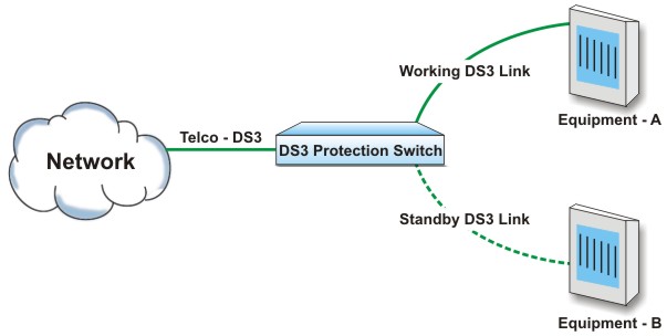
Upon failure of Equipment - A, the DS3 Telco line automatically switches to standby Equipment - B.
Application Diagram 2
Telco DS3 Line Connected to Equipment - B
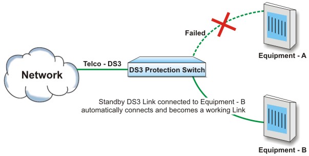
Upon failure of Equipment - A, the DS3 Telco line automatically switches to standby Equipment - B.
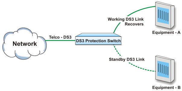
Application Diagram 3
Equipment - A recovers - Telco T1 automatically switches to Equipment - A
DS3 Failover (DS3 Automatic Protection) APS Switch - Data Sheet