
VCL-30, 2Mbps - 30 Channel E1, Drop-Insert Multiplexer
Orion Telecom Offers Power Utility Solutions Oil & Gas Networks Solutions Railway & Metro Rail Solutions PTP IEEE-1588v2 GPS Primary Reference Clock Packet Optical Transport Multiplexers Teleprotection SCADA, FOTE, OLTE Digital Cross Connects Echo Cancellers IP/Ethernet over TDM 1+1 APS (Fail-Over) Solutions Monitoring Groomer Solutions
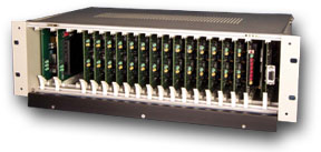
VCL-30, E1, Drop-Insert (Add-Drop) Multiplexer
Orion Telecom Networks Inc. offers The 2Mbps VCL-30, E1, Drop-Insert (Add-Drop) Multiplexer provides full range of POTS (voice) and digital data services to subscribers located at different locations, requiring to interconnect and establish a voice and data network over an E1 link. The VCL-30 is a simple, and yet a powerful channel bank for connecting and integrating analog communication equipment with digital E1 services.
- VCL-30, E1, Drop-Insert (Add-Drop) Multiplexer - (Data Sheet)
- VCL-30, E1, Drop-Insert (Add-Drop) Multiplexer - Technical Specifications
The VCL-30, E1, Drop-Insert Multiplexer provides voice telephony and digital data services which include:
- Interconnecting computer terminals
- Interconnecting LAN (Local Area Networks)
- Providing leased data lines and real-time video links to subscribers at speeds ranging from 64Kbps up to 1.024Mbps, using the "N"x64, V.35 data interface card.
- iDSL (ISDN DSL) leased line interface
- 10BaseT Ethernet G.703, co-directional, synchronous data interface @ 64Kbps
The VCL-30 E1 Interface operates at a primary rate of 2.048 MBits/Sec and provides a host of features including, channel drop and insert facility, high-speed data ports for digital communication links - including internet access, wide area networking, over a network of VCL-30, E1 multiplexers, for voice and data applications. The VCL-30 has an effective, Windows based "Network Management System", which may be used for configuring the system and subsequent remote monitoring, management and control of the inter-connected systems in the network. An extensive set of alarms, for easy maintenance are provided in the system. The system supports low speed synchronous / asynchronous V.24 interface and high speed synchronous V.35, G.703 data interfaces. The equipment also supports FXO, FXS and inter-exchange E&M interface used for inter-connecting telephone exchanges ("junction mux application").
The available data interface options include:
- G.703, co-directional, synchronous data interface @ 64Kbps.
- V.35, synchronous data interface @ 64Kbps.
- "N" x 64Kbps, V.35, user configurable, synchronous data interface. The value of "N" may by configured by the user according to bandwidth requirements. The maximum value of "N" = 16 (1.024Mbits/Sec.)
- V.24 / RS232, asynchronous data interface for low-speed data applications ranging from 300Bps to 19.2Kbps.
- iDSL (ISDN DSL) leased line interface
- 10BaseT Ethernet G.703, co-directional, synchronous data interface @ 64Kbps
- The VCL-30 offers an excellent flexibility on the choice of transmission medium over which it may be deployed. The transmission medium may be either twisted copper cable pairs, optical fiber cable, or wireless.
Features and Highlights
Features
- Voice and Digital Data services
- Any combination ("mix-n-match") of Voice and Digital Data services deployed from a single VCL-30 "Smart Shelf"
- Drop and Insert applications
- Drop / Insert of any time slot at the same location. Allows time-slot mapping.
- Modularity of a choice of interfaces ~ 2, voice or data channels per card
- All 30 channels are programmable as per user requirements
- Digital Data option may be used for internet access or videoconferencing application
- Hotline facility
- LAN to LAN bridging
- Frame Relay circuit termination
- Powerful Network Management System for monitoring and network control
- Software programmable level setting for all voice services.
- Diagnostic feature for termination cards
- Automatic bypass of a terminal during an E1 node failure when used in a "drop-insert" mode
- Microprocessor and software based design
- Compliance with all relevant ITU-T (CCITT) recommendations
- 3U high, compact construction
Highlights
- Field upgrade possible to provide voice, data or both services.
- Flexibility on use of transmission medium - copper, fiber, or wireless
- Choice of Interfaces for Data Applications
- RS-232, PC Interface for "Network Control And Management Software"
- Channel assignment independent of slot position in the subrack
- Extensive set of alarms
- User programmable alarm responses
- Programmable alarm responses
- Synchronization to different user selectable clock sources
- No forced cooling required
- Temperature Range: -10 Degree Centigrade to +65 Degree Centigrade
Transmission Mediums
The VCL-30 offers an excellent flexibility on the choice of transmission medium over which it may be deployed. The transmission medium may be either twisted copper cable pairs, optical fiber cable, or wireless.
Core System Composition
- Control Card 1
- Control Card 2
- User Choice of Interface
- Power Supply Card
- 19" Shelf and Back Plane (Back panel)
Voice Interfaces
- FXO
- FXS
- E&M (2 Wire and 4 Wire)
- FXS-FXS (Hot-line)
Data Interfaces
- RS232
- G.703 @ 64 Kbps, co-directional
- IDSL @ 128 Kbps
- V.35, n X 64 Kbps
Interface Cards
User Configurable Interface Cards
- Voice Interface: The available voice application options include;
- POTS service from a Central Office Switch (FXO, FXS)
- Hot Line (FXS - FXS)
- 2 Wire and 4 Wire, E&M interface
- Ringer
- 30W, sine-wave, 86VRMS Ringer, frequency selectable - 17Hz, 20Hz, 25Hz, 50Hz.
- For Hotline and FXS applications.
- Data Interfaces: The available data options include:
- V.35 (64Kbps Synchronous Data - 2 Interfaces per card)
- N x 64 ("N" x 64Kbps Synchronous Data - One Interface per card)
- G.703 (64Kbps Synchronous Data - 2 Interfaces per card)
- V.24 (up to 19.2Kbps Synchronous / Asynchronous Data - 2 Interfaces per card)
- iDSL (ISDN DSL) leased line interface
- 10BaseT Ethernet G.703, co-directional, synchronous data interface @ 64Kbps
Application
Applications of VCL-30
The VCL-30 is part of the digital hierarchy to provide 30 channels at 64Kbps. The individual channels are used to provide voice telephony, digital data to support point to point or networked applications and video conferencing applications. The VCL-30 is also ideal for cellular infrastructure applications, in providing cell - switch connectivity.
Other important applications include drop and insert (add-drop) facility, voice conferencing, hotline facility, high-speed data ports for digital communication links - including internet access, wide area networking and much more.
Voice Applications
The system supports a full range of voice interfaces with user programmable speech output levels, which include:
- 2 wire analog voice (FXO, FXS) interface for subscriber dial-up applications
- 2 wire and 4 wire E&M interface(s) for connecting large PABX(s), or, for inter-connecting analog telephone switches.
- Configuring any two voice (FXS-FXS) channels to provide Hotline facility
Data Applications
The VCL-30 provides 30 digital data channels @ 64Kbps per channel, to all the subscribers. The VCL-30 provides V.24 (RS232), V.35, G.703, iDSL (ISDN DSL) leased line interface and 10BaseT Ethernet G.703, co-directional, synchronous data interface @ 64Kbps.