
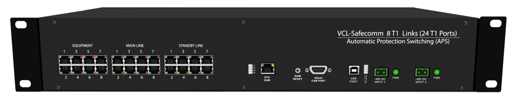
8 T1 Links (24 T1 Ports), 1+1 Automatic Protection Switching (APS) Equipment
Orion Telecom Offers Power Utility Solutions Oil & Gas Networks Solutions Railway & Metro Rail Solutions PTP IEEE-1588v2 GPS Primary Reference Clock Packet Optical Transport Multiplexers Teleprotection SCADA, FOTE, OLTE Digital Cross Connects Echo Cancellers IP/Ethernet over TDM 1+1 APS (Fail-Over) Solutions Monitoring Groomer Solutions
Product Overview
The VCL-SafeComm, 8 T1 Links (24 T1 Ports), 1+1 Automatic Protection Switching (APS) Equipment may be used to protect upto 8 T1 Links (24 T1 Ports), point-to-point links and provide an alternate communication route to each T1 Link between any two T1 points.
In the event of the failure of the primary (Main) T1 communication route, the VCL-SafeComm, 8 T1 Links (1+1 Automatic Protection Switching Equipment) automatically switches the T1 traffic to a secondary (standby) T1 route. The VCL-SafeComm, 8 T1, 1+1 Automatic Protection Switching equipment is available in a 2U high chassis which may be mounted in any DIN standard,19-Inch rack.
VCL-SafeComm, 8 T1 Links (24 T1 Ports) - Data Sheet
VCL-SafeComm, 8 T1 Links (24 T1 Ports) - Presentation
This product allows the user to design 1+1 (protected) redundant T1 routes on similar (fiber-fiber), or complementing (fiber-radio) transmission mediums.
The criterion for switching between the primary (main) and the secondary (protected/standby) routes is user programmable. Criterion for switching between the primary (main) and the secondary (protected/standby) routes may be Loss-Of-Signal on T1 links, or AIS (All-Ones AIS alarm) condition. The criterion for switching time and recovery time between the primary (main) and the secondary (protected/standby) routes is user programmable.
Data transported on the T1 Links is transparent and protocol independent.
Technical Specifications
T1 Interface
| Number of Interfaces | Total 24 T1 interfaces 8 for Main T1 Links. 8 for Primary T1 Links. 8 for Secondary T1 Links. |
| Line Rate | T1 – 1.544 Mbps |
| Line Code | B8ZS, AMI (automatic selection) |
| Frame Structure | SF, ESF (automatic selection) |
| Bit Rate | 1544 Kbps ± 50 ppm |
| Jitter Tolerance | As per ITU-T G.823 |
| Output Jitter | < 0.05 UI (in the frequency range of 20 Hz to 100 Khz) |
| Pulse Mask | As per ITU (CCITT) Rec. G.703 |
| Conformity (electrical) | G.703 |
| Nominal Impedance | 100 Ohms, balanced |
Clock
- Transparent between the two points of the T1 Links.
Management and Control
- Serial Management Port (RS232) - COM Port
- 10/100 BaseT for Remote Management over a LAN
- 10/100 BaseT Telnet over a TCP-IP Network
Specification and Regulation Compliance
- Meets CE requirements
- Complies with FCC, Part 68 and Part 15 subpart A specifications
- Safety - UL 1459 Issue 2
Command Language
- Command Line Interface (English text commands)
Alarm Contact Closures
- 1 Alarm Relay
- Type - Form "C" relay
Temperature
- Operating 0°C to 50°C
- Humidity 5% to 95% non-condens
| Rack mounting | Standard 19-Inch. DIN Rack |
| Height | 44.00 mm. |
| Depth | 260.00 mm. |
| Width | 477.00 mm. |
| Weight | 4.00 kg. |
| Output voltage of AC Adapter | 100 - 240 Volt AC |
| Range of input AC voltage | 100 V to 240 V AC, 50Hz / 60Hz. |
| System input voltage | 7.5 V DC to 9.0 V DC, DC input polarity protection. |
| Maximum full load output current | 2.5 A at 7.5 V DC/9.0 V DC |
| Input voltage reversal protection | Provided in the Card |
| Efficiency at full load | >86% |
| Input DC voltage | - 48V DC (nominal) |
| Range of input voltage | - 40V to - 60V DC |
| System voltage | + 3.3V |
| Input voltage reversal protection | Provided in the Card |
| Short circuit protection | Provided |
| Power Consumption | < 10W |
Modes of Operation
There are three modes in which the VCL-SafeComm T1, 1+1 Automatic Protection Switch can be configured to operate in:
- AUTOMATIC SWITCHING MODE
- EXTERNAL TRIGGER SWITCHING MODE
- MANUAL SWITCHING MODE
AUTOMATIC SWITCHING MODE:
- The VCL-SafeComm T1, 1+1 Automatic Protection Switch can be configured to operate in an AUTOMATIC SWITCHING MODE. In the automatic mode, the switch shall automatically switch and re-route the T1 circuits from the MAIN route to the STANDBY route if there is an AIS or a LOS (LOSS OF SIGNAL) alarm, on the MAIN T1 link route.
- Similarly, in the automatic mode the switch shall automatically switch back and re-route the T1 circuits from the STANDBY route to the MAIN route upon the restoration of the service on the MAIN T1 link route.
- All switching parameters and link restoration parameters are user programmable.
EXTERNAL TRIGGER SWITCHING MODE:
- Sometimes the user wants to switch the T1 circuits between the MAIN route and the STANDBY route when some external event occurs. In the EXTERNAL TRIGGER MODE the user can switch between the MAIN T1 route and the STANDBY T1 route when an external trigger (such as an closed/opened physical contact) is applied to the switch. This feature was added to make it compatible with certain radios equipment suppliers, where they apply an external trigger to switch and re-route the T1 circuits between their main T1 radios and standby T1 radios.
MANUAL SWITCHING MODE:
- In Manual Switching Mode, the user shall use manual Telnet commands to switch the T1 circuits between the MAIN route and the STANDBY route, manually, using Telnet commands. In this mode the AUTOMATIC MODE and the EXTERNALL TRIGGER MODE are both disabled and the manual commands over ride all other modes.
Product Application Note: 8/16 E1/T1 Links (24/48 E1/T1 Ports), 1+1 Automatic Protection Switching Equipment: This equipment is to be used when the customer wants to use two different E1/T1 links of the network to establish a 1+1 redundant path to ensure continued E1/T1 service bewteen two points even if one of the network E1/T1 link fails. Example - the customer may want to use E1/T1 Optical Fiber and an E1/T1 Radio link and to provide an ACTIVE and a STANDBY link between a BSC and a BTS so that when the E1/T1 Optical Fiber (ACTIVE) link goes down the STANBY / REDUNDANT E1/T1 Radio link automatically gets connected to provide continued connectivity and service between the BSC and the BTS.
Product Application Note: The E1/T1 Fail-Over Switch should be used when the customer is using a single E1/T1 link to provide protection equipment to the customers premises by using one E1/T1 ACTIVE and one E1/T1 STANDBY equipment (such as a ROUTER or a PBX). The E1/T1 Failover Switch shall automatically switch the E1/T1 that is being received from the telephone company between the ACTIVE E1/T1 equipment and the STANDBY E1/T1 equipment. Should the ACTIVE E1/T1 equipment go bad or be removed from service, the E1/T1 link from the telephone company automatically gets switched to the STANDBY E1/T1 equipment without any customer or user intervention.
Applications
Providing 1+1 alternate paths between any two Transmission mediums (active+standby). e.g:
- Fiber/Fiber
- Radio/Fiber
- Radio/HDSL
- Fiber/HDSL etc.
Example: The user may deploy the VCL-SafeComm, 8 T1, 1+1 Automatic Protection Switching Equipment to provide an alternate communication route between an optical fiber link and a radio link between any two points. In the event of the failure of the primary (optical fiber) link the T1 is automatically switched to the alternate route over the E1 radio, thus ensuring maximum uptime on all such 1+1 protected E1 Links.
Once the primary (optical fiber) T1 Link on the optical fiber is restored, the VCL-SafeComm, 8 T1, 1+1 Automatic Protection Switching Equipment automatically restores the communication to the primary (optical fiber) T1 Link. The switching and restoration criterion is user programmable.
Application Diagrams
| Application # 1
Features
|
|
Point-to-Point Application: May be used in a point-to-point configuration to provide 1+1 protected / Alternate Routing Path between any two point, using diverse (or similar) T1 transmission mediums.
| Application # 2 |
|
Point-to-Multipoint Application: To provide 1+1 Redundant T1 Link(s) between a single (BSC) location and multiple (BTS) locations using diverse (or similar) T1 transmission mediums.