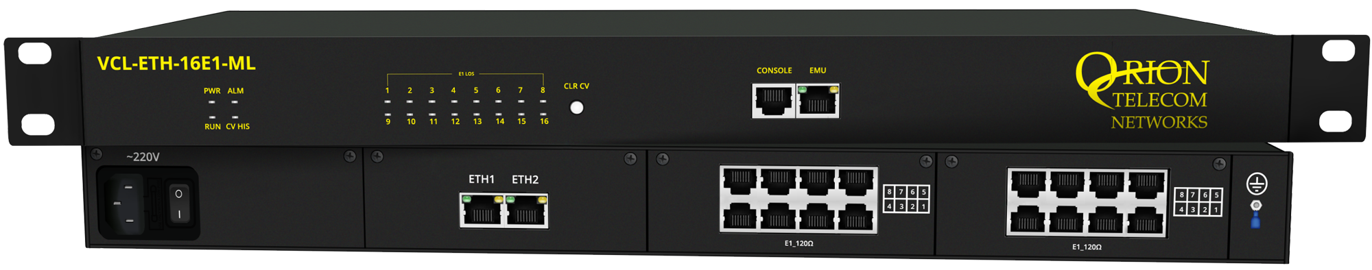
Ethernet over Multi E1 (ML-PPP) 10/100/1000BaseT to 8/16 E1 Interface Converter
Orion Telecom Offers Power Utility Solutions Oil & Gas Networks Solutions Railway & Metro Rail Solutions PTP IEEE-1588v2 GPS Primary Reference Clock Packet Optical Transport Multiplexers Teleprotection SCADA, FOTE, OLTE Digital Cross Connects Echo Cancellers IP/Ethernet over TDM 1+1 APS (Fail-Over) Solutions Monitoring Groomer Solutions
Ethernet over Multi E1 (ML-PPP) 10/100/1000BaseT to 8/16 E1 Interface Converter
Orion's VCL-ETH-8E1-ML / VCL-ETH-16E1-ML Converter allows the user to send Ethernet data between two points or between multiple points (maximum 12 directions), over 8/16 E1 Links respectively. E1 Interfaces options are 75 Ohms/120 Ohms (Optional - as per user requirement). This equipment provides two Electrical Gigabit (1000/100/10M) Ethernet Interfaces (RJ-45) ports at the customer site.
Ethernet over Multi E1 (ML-PPP) Converter - Data Sheet (PDF)
This equipment is available in the following configurations:
| E1 Interface Number | 8 or 16 |
| E1 Port Impedance option | 75 Ohms (BNC) / 120 Ohms (RJ45) - Optional |
| Power Supply Options | AC or DC or AC + DC-Redundant AC = 100 ~ 240V AC, 50 / 60 Hz DC = 18 ~72V DC |
This product is available in two versions:
| VCL-ETH-8E1-ML | 8 E1 Port Version |
| VCL-ETH-16E1-ML | 16 E1 Port Version |
The equipment can be installed (at central site) and used with other equipment (i.e. with Ethernet over Multi E1 - DLX or VCL-ETH-FE1 at remote sites) to meet various application requirements.
The Converter is an Ethernet extension device, complied to IEEE 802.3 series standards, which utilizes TDM telecom infrastructure (the telecom network of E1s, or of PDH, SDH and E1 / E3 / SDH microwave etc.), complied to ITU-T G.7041, G.7042, G.7043 and G.8040 standards, for carrying Ethernet data. It converts the Ethernet data into E1 frame format for transmission over the existing TDM (E1) links and then re-converts the E1 back into Ethernet data at the far-end terminal, to BRIDGE Ethernet LANs over the existing E1 based telecom network. The device can effectively utilize the existing TDM network to transport Ethernet data at low investment.
Application
The equipment may be used for the following purposes:
- Bridging Ethernet LANs over existing TDM (E1) telecom network
- Extending Ethernet networks utilizing TDM (E1) landline based telecom infrastructure.
- Using telecom network of E1s/PDH/SDH microwave etc. carrying E1s to transport Ethernet data.
- Interconnecting DSLAMS to Central Routers over PDH/SDH telecom networks.
- Interconnecting IP-based GSM base stations.
- Interconnecting WiMax base stations.
Features and Highlights
Features and Highlights
- Supports point to multipoint, up to 12 directions and 16 E1 Links capacity
- 1U high compact size
- Provides 2 x Electrical Gigabit Ethernet 10/100/1000BaseT Ports with each converter
- Supports Auto Adaptive three working modes of E1 transmission. Un-Framed (Transparent), Framed PCM 30 and Framed PCM 31 formats (Auto Sensing)
- Supports VCAT (virtual concatenation) and LCAS (Link Capacity Adjustment Scheme) protocol, and complies with ITU-T G.7042 Specifications
- Supports auto removal of down E1 link and auto insertion of recovered E1 link
- Mapping to E1 complies with ITU-T G.7043 an d G.8040 specifications
- Supports VLAN tagging as per 802.1Q
- User selectable ports for enabling / disabling the QoS service
- Supports differential delay of up to 220ms on E1 Links
- Complies with IEEE 802.3ab, IEEE 802.3u and IEEE 802.3 specifications.
- Supports X.86, LAPS and HDLC transmission protocols.
- Supports 10M / 100M, Half / Full duplex and auto-negotiate mode
- Configurable frame size upto 1552 bytes (MTU size)
- Supports GFP-F encapsulation complying with ITU-T G.7041
- Provides automatic smooth adjustment of Ethernet bandwidth as per the availability of carrier (E1) links
- Provides error frame statistic
- Supports automatic removal and addition of E1 Links without interrupting current services
- Available with MAC address list filtration, learning and updating functions
- A large external SDRAM buffering for handling data bursts
- 8000 MAC address learning
- Support configurable MAC aging time 12 / 300 seconds
- Supports internal synchronization clock
- Automatic straight and cross-over cable support (Auto-MDI/X).
Salient Features
- Connect multiple sites (up to 12 directions) from a single central location
- Data rate recovery after restoration of lost E1 (LCAS)
- Automatic data rate management according to number of available E1 links
- Maximum cable length supported (upto 1000 feets / 333 meters)
- Support unbalanced bandwidth- If Rx line of some E1 links are not working then the equipment will keep working on Tx line, to use unbalanced bandwidth. i.e. If Tx of a E1 line is not working out of 5 E1 available then the equipment will continue to send data on 4 E1s and receive on 5 E1s and vice-versa.
Alarms and Indicator Monitoring
- Power Indicator
- Run (in-operation) Indicator
- General Alarm Indicator for E1 and Ethernet Link
- E1 LOS Alarm for individual E1 port (1-16)
- Code Violation History (CV_HIS) Alarm on E1 port
- Ethernet Link Indicator
- Ethernet Speed Indicator
- SNMP Diagnostic and Monitoring.
Management Control
- 10/100BaseT Ethernet management interface
- RS232 serial management interface
- Remote (Telnet) management interface
- Windows XP - based Graphical User Interface (GUI)
- Windows 7 - based Graphical User Interface (GUI)
- SNMP V2 Monitoring
- NMS (Network Management System) for monitoring multiple units from a single / central location.
Applications
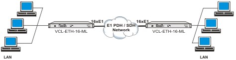
Application Diagrams
Application # 1
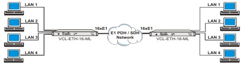
Application # 2
Application # 3
Application # 4
Application # 5