
4 Ethernet over E1
E1/4*10(100)Base-T Interface Converters
Orion Telecom Offers Power Utility Solutions Oil & Gas Networks Solutions Railway & Metro Rail Solutions PTP IEEE-1588v2 GPS Primary Reference Clock Packet Optical Transport Multiplexers Teleprotection SCADA, FOTE, OLTE Digital Cross Connects Echo Cancellers IP/Ethernet over TDM 1+1 APS (Fail-Over) Solutions Monitoring Groomer Solutions
4 Ethernet over E1
E1/4*10(100)Base-T Interface Converters
Description
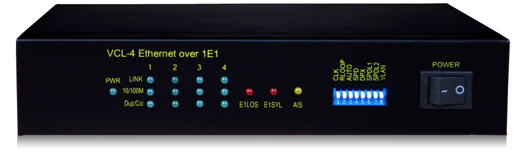
Orion Telecom Networks Inc. offers the VCL-4 Ethernet over E1 Converter provides the user with an option to transport Ethernet (multiple LANs) over an E1 link. The equipment converts and transports upto 4 x Ethernet links over an E1 in a shared* mode or a discreet* mode, depending on the users preference and selection.
4 Ethernet over E1 - Data Sheet (PDF)
Power Point Presentation (PPS)
In the shared* mode (please see application diagram below) all 4 Ethernet channels are transported over the same shared E1 link and are allowed full access to each other’s path. The user may select this mode if the user desires that all of the 4 x Ethernet links that are being transported over the same E1 to optimally share its bandwidth resources and where discretion is not consequential.
In the discreet* mode (please see application diagram below) all 4 Ethernet channels are transported over the same E1 link without intrusion or access to each others path without any sharing. The user may select this mode if the user desires that all of the 4 x Ethernet links that are being transported over the same E1 to maintain discretion without allowing access to each other.
The equipment shall always be installed and used in pairs, with one terminal being installed at either end (each side) of the network.
The VCL-4 Ethernet over E1, E1/4*10(100)Base-T Interface Converter is an ethernet extension device utilizing TDM telecom infrastructure (the telecom network of E1s, or of PDH, SDH and E1/E3/SDH microwave etc. carrying E1s).
The VCL-4 Ethernet over E1, E1/4*10(100)Base-T Interface Converter converts the Ethernet Data into E1 frame format for transmission over the existing TDM (E1) links and then reconverts the E1s back into Ethernet Data at the far-end terminal. It function is to primarily provide a BRIDGE between two Ethernet LANs over the existing E1 based telecom network.
The device can effectively utilize the redundant bandwidth of telecom operators’ existing TDM network to transport Ethernet data with low investment.
Application Diagram
This equipment may be used for the following purposes:
Bridging Ethernet LANs over existing TDM (E1) telecom network.
- Extending Ethernet Networks utilizing TDM (E1) landline based telecom infrastructure.
- Using telecom network of E1s / PDH / SDH Microwave etc. carrying E1s to transport Ethernet Data.
- In all these cases the equipment be always installed and used in pairs, with one terminal being installed at either end (each side) of the network
Application Diagram
Application 1: Shared Link Mode
In the “shared link mode”, each LAN can view and talk to other LANs. Example: each LAN can view and talk to all other LANs at same site or the corresponding remote side. This mode may be selected for use if bandwidth optimization and usage is of prime importance and the user is not averse to sharing the E1 link resources with the other LANs being transported on the same E1 link.

Note: In the “shared link mode”, the VLAN switch must be OFF (The ethernet ports are not isolated to each other on both sides of the E1 link. Please refer to page 6 for VLAN switch settings.
Application 2: Discrete Link Mode
In the “discrete link mode”each LAN is bridged to, and can only talk to its corresponding LAN on the remote side. It can not talk to any other LAN either at same side or the remote side. This mode may be selected for use if the users do not wish to share the E1 link resources with the other LANs being transported on the same E1 link.

Example: In the discrete link mode, the LAN 1 (Ethernet Port 1 of the equipment) only can talk to the corresponding LAN 1 (Ethernet Port 1 of the equipment) at remote side and can not talk to any other LAN, either on remote side or same side.