|
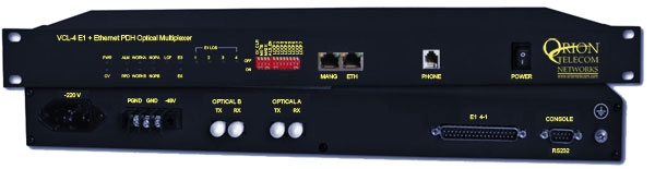
4 E1 Optical Multiplexer plus
Ethernet with SNMP
Product Overview
Orion Telecom Networks
Inc. offers 4 E1 + Ethernet -
Optical Multiplexer is a high performance optical line transmission
equipment, combines 4, ITU-T G.703 compliant standard electrical E1s
plus 100BaseT ethernet signal into an optical data stream for
transport over fiber optic pairs. Several transmitter options for
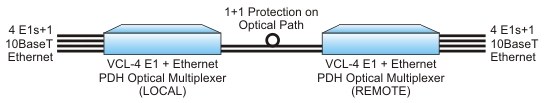
different cable types and wave-lengths are available. 1+1 optical
path redundancy is offered and available as an option.
The option of 1+1 Optical
Redundancy (Protection Switching), the transmission automatically
switches to a 'standby' optical link in the event of a failure of
the 'primary' optical link.
Application Diagram
|
 |
Features
-
Compact design (1U
- 44mm high) that performs E1 and Ethernet channel multiplexing &
de-multiplexing to an optical output
-
Provides visible and
audible alarm indication
-
Orderwire (EOW)
channel for end to end installation and maintenance
-
Local and remote loop
back test for diagnostics
-
1+1 Fiber Path
protection
-
Clock options:
internal/loop-timed
-
Provides visible and
audible alarm indications
-
Local & remote
loopback controls for diagnostics and troubleshooting
-
Local configuration
management through RS232 Serial Port
-
Low power consumption
Highlights
-
Integrated E1 plus Ethernet - optical
multiplexer
-
10/100M Ethernet port - 100Mbps Ethernet
data transmission rate
-
Powered by grade Class I Laser
-
4E1 interfaces
-
Power Input options: -48V DC input, AC,
AC+DC
-
E1 120 Ohms / 75 Ohms - options available
-
SNMP
-
Remote configuration
and management through 10/100BaseT Ethernet Port - Telnet
-
Extensive alarms and status indication
facility
-
Easy operation
-
Standard ITU-T compliant interfaces
-
Auto Laser Shut Off facility.
|
|
Others Links
Technical specifications are subject to
change without notice.
All brand names and trademarks are the property of their respective owners.
|
|
|
|
|
|